AB763 (Twin Reverb-style) Blackface Twin Reverb‑style · 1963–1967 · 85 W

✓ verified 2026-08-08
Schematic — redrawn in KiCad · scroll to zoom, drag to pan
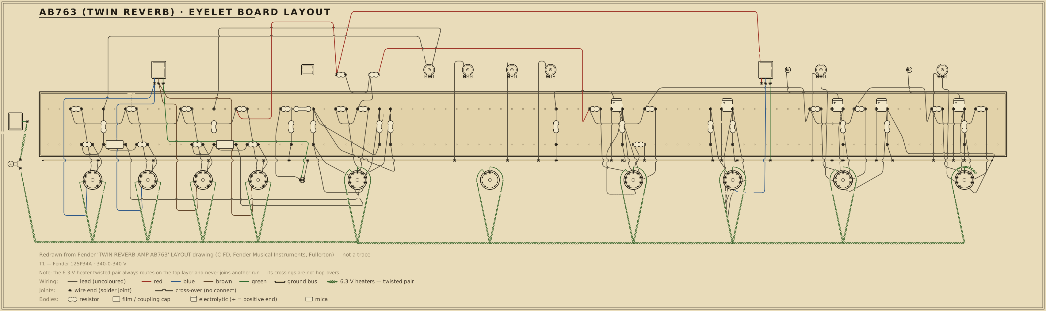
Board layout — redrawn reference diagram · source noted on the drawing Print sheet ↗
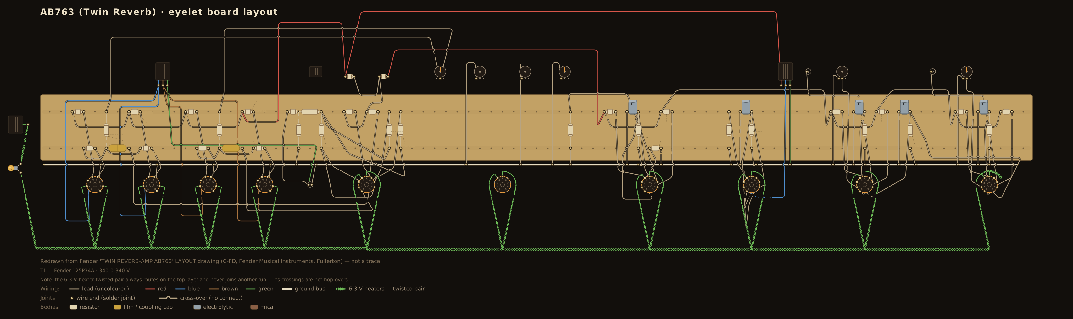
AB763 (Twin Reverb-style) eyelet board layout — an original diagram redrawn from the published layout drawing, showing the principal parts in the order that drawing places them on the board, drawn in the period layout-sheet style with each value lettered on the part.

Scroll the drawing sideways to read the whole board — the source line and the colour legend run along the bottom of the sheet — or open the full-size diagram in its own tab. Values are lettered on the parts in the period shorthand — .02-400, 250-5, 1MEG: how to read it.

Machine-checked wiring. Every modelled part the operating-point netlist places on this board has been verified in CI, terminal for terminal, to be electrically equivalent to the simulated netlist this circuit is verified against. This diagram documents connectivity and part arrangement — it is not a dimensioned 1:1 build template.

Details

The modelled parts are the tube sockets, the plate, cathode and grid-leak resistors, the power-rail droppers, and the coupling and bypass capacitors whose two leads are both named DC nodes; the check proves the same net structure, with no missing or extra connections. Parts outside that DC model — the volume / tone / mixer control-network internals, the negative-bias front end, and the heater chain, pilot lamp and power-transformer / rectifier AC side — are drawn from the cited sources but are not machine-checked; the CI report enumerates every one of their terminals so the boundary is explicit rather than silent.

Board and part positions are drawn at diagram scale, and lead dress, grounding paths, and physical spacing all matter in a high-voltage chassis. If you build from it, verify every connection against the schematic above and the operating-point table below as you go.

Operating point vs. published chart

Chart values read from the published drawing — or, where the drawing carries no voltage chart, from the cited published measurements (never reproduced). The simulated column is this circuit's own netlist solved in ngspice by the run that gates it; every deviation beside it is those two numbers compared, not a separately stated figure. Tolerances are this project's verification targets: tube-pin nodes carry the tolerance the cited source states, or ±20% — the era's printed convention — where it states none, and power rails are held to tighter internal targets. Every gated node lands within target — worst deviation 14.9%.

Node Chart Simulated Deviation Tolerance Note
BC 450 V 445.7 V 1.0% ±8% node [C], the phase-inverter plate supply — solved from BB through the drawing's 1 kOhm-1W dropper
BD 410 V 407.8 V 0.5% ±8% node [D], the preamp plate supply feeding all six 100 kOhm plate loads — solved from BC through the 4.7 kOhm-1W dropper
S61 458 V 457.6 V 0.1% ±8% 6L6GC screen after its 470 Ohm-1W stopper, off the post-choke node BB
G61 −52 V −52.0 V 0.0% ±8% 6L6GC grid, fixed bias via a shared 220 kOhm leak and a 1500 Ohm stopper from the -52 V supply
PRD 440 V 457.2 V 3.9% ±20% reverb-driver 12AT7 plate (both sections paralleled), off BB through the TR4 primary DCR
KRD 8.6 V 9.1 V 5.5% ±20% reverb-driver 12AT7 shared cathode over 2.2 kOhm
PN1 260 V 269.8 V 3.8% ±20% Normal-channel input plate, 100 kOhm from +410
KN1 2 V 2.1 V 3.6% ±20% Normal-channel input cathode over 1.5 kOhm
PV1 250 V 269.8 V 7.9% ±20% Vibrato-channel input plate, 100 kOhm from +410
KV1 2 V 2.1 V 3.6% ±20% Vibrato-channel input cathode over 1.5 kOhm
PN2 270 V 275.7 V 2.1% ±20% Normal-channel 2nd stage plate, 100 kOhm from +410
PV2 240 V 275.7 V 14.9% ±20% Vibrato-channel 2nd stage plate, 100 kOhm from +410
KA 2 V 2.2 V 8.3% ±20% the 820 Ohm / 25 uF cathode network the two channels' second stages SHARE (drawing box [A]); the drawing prints +2.0 V at both ends of it
PR1 275 V 275.7 V 0.3% ±20% reverb-recovery plate, 100 kOhm from +410
PD1 280 V 275.7 V 1.5% ±20% reverb/dry mix-driver plate, 100 kOhm from +410
KE 2 V 2.2 V 8.3% ±20% the 820 Ohm / 25 uF cathode network the recovery and mix-driver stages SHARE (drawing box [E]); printed +2.0 V at both ends
PPIA 245 V 254.7 V 4.0% ±20% PI plate, 82 kOhm (hot) side
PPIB 235 V 248.2 V 5.6% ±20% PI plate, 100 kOhm (cold) side
KPI 100 V 97.1 V 2.9% ±20% PI joined cathodes, above the 470 Ohm
JPI 98 V 95.0 V 3.0% ±20% PI tail junction (470 Ohm / 22 kOhm), grid-leak return

Tube-pin nodes are checked at the tolerance the cited source states, or at the era's ±20% convention where it states none; power-rail nodes are held to tighter internal verification targets. Simulated figures are the netlist's DC solution, not measurements from a chassis.

The output stage behind these numbers can be drawn: the load line explorer plots this circuit's 6L6GC quartet at the DC operating point its netlist carries — 460 V on the plates with a −52 V grid bias — and marks where the load line crosses.

Parts list

Every designator in this list appears on the schematic above, and every designator on the schematic appears here — the two are checked against each other in both directions, a valve's two halves counting as one bottle (V1A and V1B are both V1). The schematic draws one jack per channel input pair; the chassis carries two per channel. Two cathode networks are SHARED between stages and appear once here, under the boxed node letter the drawing gives them: RKA/CKA ([A], the two channels' second stages) and RKE/CKE ([E], reverb recovery and mix driver). The tremolo tube's parts are listed, but neither of its halves has a static DC point, so both are excluded from the netlist (see notes.md). The main rectifier is silicon: two three-diode strings off the 340-0-340 V winding.

RefPartValue / ratingRole
R1n Carbon comp resistor 68 kΩ · ½ W Normal input grid stopper (jack 1)
R2n Carbon comp resistor 68 kΩ · ½ W Normal input grid stopper (jack 2)
RGN1 Carbon comp resistor 1 MΩ · ½ W Normal input grid leak
RLN1 Carbon comp resistor 100 kΩ · ½ W Normal input plate load
RKN1 Carbon comp resistor 1.5 kΩ · ½ W Normal input cathode bias
CKN1 Electrolytic capacitor 25 µF · 25 V Normal input cathode bypass
CTN Mica capacitor 250 pF Normal treble cap
VRTN Potentiometer 250 kΩ-A Normal treble
RSN Carbon comp resistor 100 kΩ · ½ W Normal tone-stack slope resistor
CBN Coupling capacitor 0.1 µF Normal tone-stack bass cap, slope node to the bass pot
VRBN Potentiometer 250 kΩ-A Normal bass
CBN2 Coupling capacitor 0.047 µF Normal tone-stack middle-leg cap, slope node to the middle pot
VRMN Potentiometer 10 kΩ-A Normal middle
VRVN Audio-taper potentiometer 1 MΩ-A Normal volume
CBRN Mica capacitor 120 pF Normal bright cap, across the volume pot (switched)
RLN2 Carbon comp resistor 100 kΩ · ½ W Normal 2nd-stage plate load
CCN2 Coupling capacitor 0.047 µF Normal 2nd-stage output coupling
R1v Carbon comp resistor 68 kΩ · ½ W Vibrato input grid stopper (jack 1)
R2v Carbon comp resistor 68 kΩ · ½ W Vibrato input grid stopper (jack 2)
RGV1 Carbon comp resistor 1 MΩ · ½ W Vibrato input grid leak
RLV1 Carbon comp resistor 100 kΩ · ½ W Vibrato input plate load
RKV1 Carbon comp resistor 1.5 kΩ · ½ W Vibrato input cathode bias
CKV1 Electrolytic capacitor 25 µF · 25 V Vibrato input cathode bypass
CTV Mica capacitor 250 pF Vibrato treble cap
VRTV Potentiometer 250 kΩ-A Vibrato treble
RSV Carbon comp resistor 100 kΩ · ½ W Vibrato tone-stack slope resistor
CBV Coupling capacitor 0.1 µF Vibrato tone-stack bass cap, slope node to the bass pot
VRBV Potentiometer 250 kΩ-A Vibrato bass
CBV2 Coupling capacitor 0.047 µF Vibrato tone-stack middle-leg cap, slope node to the middle pot
VRMV Potentiometer 10 kΩ-A Vibrato middle
VRVV Audio-taper potentiometer 1 MΩ-A Vibrato volume
CBRV Mica capacitor 120 pF Vibrato bright cap, across the volume pot (switched)
RLV2 Carbon comp resistor 100 kΩ · ½ W Vibrato 2nd-stage plate load
CCV2 Coupling capacitor 0.02 µF Vibrato 2nd-stage output coupling
RKA Carbon comp resistor 820 Ω · ½ W Cathode bias SHARED by both channels' second stages ([A])
CKA Electrolytic capacitor 25 µF · 25 V Bypass for the shared second-stage cathode ([A])
CRS Mica capacitor 500 pF Reverb send coupling to the driver grid
RGRD Carbon comp resistor 1 MΩ · ½ W Reverb-driver 12AT7 grid leak
RKRD Carbon comp resistor 2.2 kΩ · ½ W Reverb-driver shared cathode bias (both sections paralleled)
CKRD Electrolytic capacitor 25 µF · 25 V Reverb-driver cathode bypass
T4 Reverb transformer Fender 125A20B Reverb driver → tank input
RGR1 Carbon comp resistor 220 kΩ · ½ W Reverb-recovery grid resistor (tank output)
RLR1 Carbon comp resistor 100 kΩ · ½ W Reverb-recovery plate load
CCR1 Coupling capacitor 0.003 µF Reverb-recovery output coupling
VRREV Linear potentiometer 100 kΩ-L Reverb level
RMR Carbon comp resistor 470 kΩ · ½ W Reverb mix resistor
RGD1 Carbon comp resistor 3.3 MΩ · ½ W Mix-driver grid resistor in the dry path (tremolo shunt node)
CBD1 Mica capacitor 10 pF Bright cap across the mix-driver grid resistor
RLD1 Carbon comp resistor 100 kΩ · ½ W Mix-driver plate load
CCD1 Coupling capacitor 0.1 µF Mix-driver output coupling
RKE Carbon comp resistor 820 Ω · ½ W Cathode bias SHARED by the reverb recovery and the mix driver ([E])
CKE Electrolytic capacitor 25 µF · 25 V Bypass for the shared recovery/mix-driver cathode ([E])
RMIXN Carbon comp resistor 220 kΩ · ½ W Normal-channel mixing resistor
RMIXV Carbon comp resistor 220 kΩ · ½ W Vibrato-channel mixing resistor
CPIA Coupling capacitor 0.001 µF Mixer node → PI hot grid
VRSPD Reverse-audio potentiometer 3 MΩ-RA Tremolo speed
VRINT Reverse-audio potentiometer 50 kΩ-RA Tremolo intensity
RTO1 Carbon comp resistor 220 kΩ · ½ W Tremolo oscillator plate load
RKTO1 Carbon comp resistor 2.7 kΩ · ½ W Tremolo oscillator cathode bias
CKTO1 Electrolytic capacitor 25 µF · 25 V Tremolo oscillator cathode bypass
RTOG1 Carbon comp resistor 1 MΩ · ½ W Tremolo phase-shift resistor
RTOG2 Carbon comp resistor 1 MΩ · ½ W Tremolo phase-shift resistor
RTOG3 Carbon comp resistor 2.2 MΩ · ½ W Tremolo oscillator grid resistor
RTOG4 Carbon comp resistor 220 kΩ · ½ W Load to ground at the reverb/dry mix node, where the photocell shunts the signal
RTOSP Carbon comp resistor 100 kΩ · ½ W Tremolo speed-network series resistor
CTO1 Film capacitor 0.01 µF Tremolo phase-shift cap
CTO2 Film capacitor 0.01 µF Tremolo phase-shift cap
CTO3 Film capacitor 0.02 µF Tremolo oscillator → lamp-driver coupling
RTO10 Carbon comp resistor 10 MΩ · ½ W Lamp-driver plate bleeder to the +458 V node
RKTO2 Carbon comp resistor 100 kΩ · ½ W Lamp-driver cathode bias
CKTO2 Electrolytic capacitor 25 µF · 25 V Lamp-driver cathode bypass
RLAMP Carbon comp resistor 100 kΩ · ½ W Neon-lamp series resistor to the +458 V node
OPTO Optocoupler neon lamp + photoresistor Tremolo modulator (shunts the mix-driver grid)
RLPA Carbon comp resistor 82 kΩ · ½ W · 5% PI plate load (hot side)
RLPB Carbon comp resistor 100 kΩ · ½ W · 5% PI plate load (cold side)
RGPA Carbon comp resistor 1 MΩ · ½ W PI grid leak (hot), returned to the tail junction
RGPB Carbon comp resistor 1 MΩ · ½ W PI grid leak (cold), returned to the tail junction
RTAIL Carbon comp resistor 470 Ω · ½ W PI cathode resistor
RT22 Carbon comp resistor 22 kΩ · ½ W PI tail, junction → feedback node
CPIB Coupling capacitor 0.1 µF · 200 V PI cold-grid reference to the feedback node
RFB2 Carbon comp resistor 820 Ω · ½ W Negative feedback, OT secondary → feedback node
RFB1 Carbon comp resistor 100 Ω · ½ W Feedback divider leg to ground
C1 Coupling capacitor 0.1 µF · 400 V PI hot plate → the V7/V8 grid pair
C2 Coupling capacitor 0.1 µF · 400 V PI cold plate → the V9/V10 grid pair
RGL1 Carbon comp resistor 220 kΩ · ½ W · 5% Grid leak for the V7/V8 pair, from the −52 V bias line
RGL2 Carbon comp resistor 220 kΩ · ½ W · 5% Grid leak for the V9/V10 pair, from the −52 V bias line
RST1 Carbon comp resistor 1.5 kΩ · ½ W V7 grid stopper
RST2 Carbon comp resistor 1.5 kΩ · ½ W V8 grid stopper
RST3 Carbon comp resistor 1.5 kΩ · ½ W V9 grid stopper
RST4 Carbon comp resistor 1.5 kΩ · ½ W V10 grid stopper
RSC1 Wirewound resistor 470 Ω · 1 W V7 screen resistor
RSC2 Wirewound resistor 470 Ω · 1 W V8 screen resistor
RSC3 Wirewound resistor 470 Ω · 1 W V9 screen resistor
RSC4 Wirewound resistor 470 Ω · 1 W V10 screen resistor
T3 Output transformer Fender 125A29A Parallel push-pull primary for four 6L6GC; 4 Ω secondary into two speakers, with the feedback tap
T1 Power transformer Fender 125P34A · 340-0-340 V HT (with bias tap) + 6.3 V heaters
T2 Filter choke Fender 125C1A Reservoir → screen/post-choke node [B]
DHT Rectifier (HT) silicon diode (×6) Full-wave rectifier, three series diodes per leg
C10 Electrolytic capacitor 70 µF · 350 V Reservoir filter, upper half of the series pair
C11 Electrolytic capacitor 70 µF · 350 V Reservoir filter, lower half of the series pair
RBAL1 Carbon comp resistor 220 kΩ · 1 W Reservoir balancing resistor (upper)
RBAL2 Carbon comp resistor 220 kΩ · 1 W Reservoir balancing resistor (lower)
C12 Electrolytic capacitor 20 µF · 525 V Filter, node [B] (+458, screens)
C13 Electrolytic capacitor 20 µF · 525 V Filter, node [C] (+450, PI plates)
C14 Electrolytic capacitor 20 µF · 525 V Filter, node [D] (+410, preamp plates)
RD1 Wirewound resistor 1 kΩ · 1 W Rail dropper [B] → [C]
RD2 Wirewound resistor 4.7 kΩ · 1 W Rail dropper [C] → [D]
RBIAS Wirewound resistor 470 Ω · 1 W Bias-supply series resistor off the transformer's bias tap
DBIAS Rectifier (bias) silicon diode Bias-supply rectifier
CB1 Electrolytic capacitor 25 µF · 50 V Bias-supply filter
VRBAL Linear potentiometer 10 kΩ-L Bias balance control; its wiper sets the −52 V grid line
RB2 Carbon comp resistor 27 kΩ · ½ W Bias divider leg to ground
CDEATH Ceramic capacitor 0.047 µF · 600 V Ground-switch cap (period; not in modern builds)
V1 Preamp tube 12AX7 (7025) Normal channel input + 2nd stage
V2 Preamp tube 12AX7 (7025) Vibrato channel input + 2nd stage
V3 Preamp/driver tube 12AT7 Reverb driver (both sections paralleled)
V4 Preamp tube 12AX7 (7025) Reverb recovery + reverb/dry mix driver
V5 Preamp tube 12AX7 Tremolo oscillator + lamp driver (DC point excluded)
V6 Preamp/driver tube 12AT7 Long-tailed-pair phase inverter
V7 Power tube 6L6GC Push-pull output (hot phase)
V8 Power tube 6L6GC Push-pull output (hot phase)
V9 Power tube 6L6GC Push-pull output (cold phase)
V10 Power tube 6L6GC Push-pull output (cold phase)

Circuit story

Fender's flagship of the blackface years and the reference for a loud clean amplifier: 85 watts from four 6L6GC output tubes into a pair of 12-inch speakers, with the same spring reverb and tube tremolo the smaller reverb amps carry. The circuit ran from 1963 to 1967. Two channels — a plain Normal and a Vibrato channel with the reverb and the tremolo — each get a full three-knob tone stack and a switched bright cap, and both feed one long-tailed pair driving the output quartet. There is no rectifier tube: the high tension is rectified by silicon, three series diodes to a leg.

The preamp bottles are marked 7025 on the drawing, the low-noise selected version of the 12AX7; the reverb driver and the phase inverter are 12AT7s, chosen for the current they can deliver, and the tremolo runs on its own 12AX7.

Signal path

Both channels, up to the volume control. Two inputs (each a 68 kΩ stopper on a 1 MΩ leak) → a 12AX7 stage (100 kΩ plate load, 1.5 kΩ cathode with a 25 µF bypass) → a three-knob tone stack — 250 pF treble capacitor and 100 kΩ slope resistor both leaving the plate node, 0.1 µF to the node shared by the treble pot's lower lug and the bass pot, 0.047 µF down to the 10 kΩ middle control, and the treble wiper alone as the output — → a 1 MΩ volume with a 120 pF bright cap across it on a switch.

Normal channel. Volume → a second 12AX7 stage (100 kΩ plate) → a 0.047 µF coupler into a 220 kΩ mixing resistor. No reverb, no tremolo.

Vibrato channel. Volume → a second 12AX7 stage (100 kΩ plate) → a 0.02 µF coupler into the reverb and tremolo section.

Two cathodes, four triodes

The drawing marks nodes that appear in more than one place with a boxed letter, and two of those letters carry cathodes rather than supply rails. Each ties a pair of stages onto one 820 Ω resistor and one 25 µF bypass can:

  • the Normal channel's second stage and the Vibrato channel's second stage;
  • the reverb-recovery stage and the reverb/dry mix driver.

Both ends of each pair are printed at the same +2.0 V, which is what a shared node means. The consequence is worth stating plainly: the two stages on a shared resistor are not independent. Each one's current sets the other's bias, so the two are half as deeply biased as a private 820 Ω would make them, and anything that changes one — a swapped tube, a hotter section — moves the other with it.

Reverb and tremolo

Reverb. A 500 pF capacitor sends the vibrato channel's signal to a 12AT7 with both triodes in parallel (1 MΩ grid leak, 2.2 kΩ shared cathode) feeding the 125A20B transformer and the spring tank. What comes back is recovered by a 12AX7 stage across a 220 kΩ tank leak, coupled out by 0.003 µF, and blended with the dry signal by the 100 kΩ Reverb control through a 470 kΩ mixing resistor.

Tremolo. The tremolo tube is a 12AX7 doing two jobs. One triode is a phase-shift oscillator (220 kΩ plate load, 2.7 kΩ cathode, Speed on a 3 MΩ control); the other drives the neon lamp inside an optocoupler, sitting at the top of a 100 kΩ feed from the supply with a 10 MΩ bleeder across its plate. The lamp faces a photoresistor which, through the 50 kΩ Intensity control, periodically shunts the mix driver's grid toward ground and swings the volume.

Mixing and inversion. The mix driver (100 kΩ plate, its grid fed through 3.3 MΩ with 10 pF across it) is coupled out by 0.1 µF into the vibrato channel's own 220 kΩ mixing resistor. The two channels' mixing resistors meet, and a single 0.001 µF capacitor carries the sum to the phase inverter's grid.

Phase inverter and output. A 12AT7 long-tailed pair — 82 kΩ and 100 kΩ 5% plate loads, a 470 Ω cathode resistor down to a tail junction, 22 kΩ from that junction onward, and both 1 MΩ grid leaks returned to it — splits the signal for the four 6L6GC. The tail does not run straight to ground: it lands on the negative-feedback node, where an 820 Ω resistor comes back from the speaker and a 100 Ω leg goes to ground, so the feedback arrives in the tail. The output tubes are fixed-biased at −52 V through two 220 kΩ leaks — one per phase, each feeding two tubes — with a 1.5 kΩ stopper on every grid and a 470 Ω · 1 W resistor on every screen.

Power

340-0-340 V (power transformer 125P34A) → a silicon full-wave rectifier, three series diodes to a leg → the standby switch → a reservoir of two 70 µF · 350 V cans in series, balanced by a pair of 220 kΩ · 1 W resistors → +460 V at the output-transformer centre tap and the 6L6GC plates → the 125C1A choke → +458 V at the screens, the reverb-transformer feed and the tremolo → a 1 kΩ · 1 W dropper → +450 V at the phase-inverter plates → a 4.7 kΩ · 1 W dropper → +410 V feeding all six preamp plate loads, on 20 µF · 525 V cans. The grid line comes from the transformer's bias tap through a 470 Ω · 1 W resistor, a rectifier and a 25 µF · 50 V can, to a 10 kΩ balance control over a 27 kΩ leg whose wiper sets the −52 V.

The AB763 designation, twice

Fender put "AB763" on more than one drawing. The blackface Deluxe Reverb carries it too, and the two amps share the generation's recipe — fixed bias, a long-tailed-pair inverter, tube reverb and tremolo, the same tone-stack ladder — but they are not the same circuit and neither is descended from the other. The Deluxe Reverb is a cathode-cool 22-watt amp on two 6V6GTs, a GZ34 rectifier and two-knob tone stacks; this is an 85-watt amp on four 6L6GCs, silicon rectification, three-knob stacks, and a preamp with two extra gain stages to feed them. The archive keeps the bare ab763 for the Deluxe Reverb, which reached it first, and qualifies this one by its model.

The circuit this amp actually descends from is the blonde 6G8-A Twin — four bottles, fixed bias, solid-state rectification and a long-tailed pair were all in place before the blackface redesign added the reverb and the middle controls.

Reading against the printed chart

The drawing prints a full voltage chart, every value set at ±20 %, read to ground with an electronic voltmeter. Two nodes are held at their printed values in simulation — the +460 V reservoir and the +458 V node after the choke — and everything below them is solved through the drawing's own droppers, so the two lower rails are a test of the chart rather than an input to it. They pass: the phase-inverter supply lands at +446 V against a printed +450 V and the preamp supply at +408 V against +410 V, which is the arithmetic of six 100 kΩ plate loads and a phase inverter agreeing with the resistors Fender specified.

Every node on the chart falls inside the drawing's own ±20 % across the modelled stages: the reverb driver, the four preamp stages, the recovery and mix driver, the phase inverter's +100 V cathodes and +98 V tail junction, and the screens and grids of the output quartet. The widest gap is the vibrato channel's second stage, whose plate simulates about 15 % above its printed +240 V — and that is the shared-cathode node showing itself, because the chart prints +270 V at the other end of the same 820 Ω and two stages on one resistor cannot in fact sit 30 V apart.

This circuit is published as verified: every node the chart prints for a modelled stage is compared, none is set aside as disputed, and the worst gap is the one described just above.

The tremolo tube is left out of the DC solution, both halves. The oscillator is a running phase-shift circuit whose printed +2.0 V cathode is a grid-leak-detected average rather than a quiescent point, and the lamp driver's printed +380 V plate and +5.6 V cathode are what a meter reads while the neon lamp fires and extinguishes. Neither is a static operating point, so both are reported here rather than fitted to the chart. Unlike the Deluxe Reverb's tremolo, this one hangs off the +458 V node rather than the preamp rail, so leaving it out shifts nothing else on the chart.

The output quartet is simulated on a clean-room 6L6GC model fitted to RCA's own tabulated Class A1 characteristics for that tube. It idles at about 30 mA a bottle on the +460 V rail — a little under half the tube's 30 W plate rating, and well inside its 500 V ceiling.

Sources