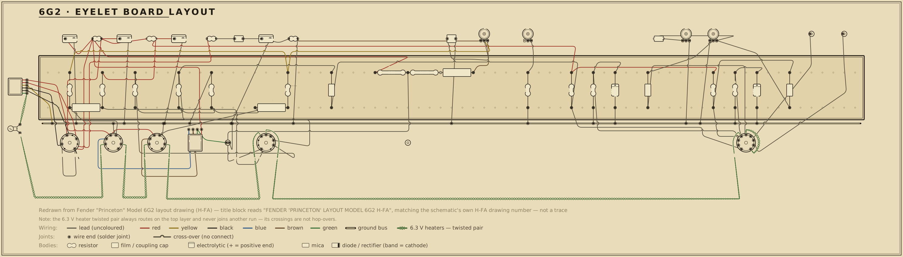
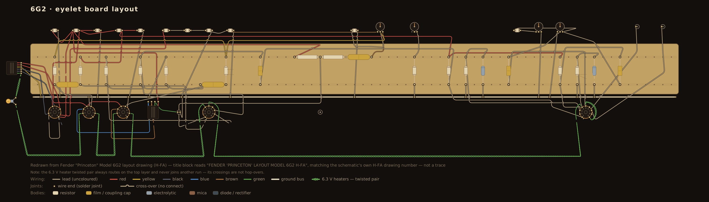
The Princeton line's hard break. For fifteen years the Princeton had been, in
Fender's own framing, a Champ with a tone control — a single-ended 6V6 student
amp tracking the Champ's own revisions through the tweed 5F2-A. The brownface
6G2 (1961–63) abandons that architecture entirely: a fixed-bias push-pull
pair of 6V6GTs, a cathodyne phase inverter to drive them, and a tremolo — a
fundamentally different, more powerful power stage, not a revision of the
single-ended one. The 5F2-A's own circuit story warns readers not to read its
values onto anything from the 6G2 forward, and this page is why: no lineage
arrow is drawn to the 5F2-A. The line the 6G2 does start runs forward to the
blackface AA964 Princeton, which keeps this circuit's fixed-bias 6V6 pair,
its cathodyne, and its bias-vary tremolo almost unchanged.
The drawing labels the first bottle 7025, the low-noise selected version of
the 12AX7; the second small bottle is a plain 12AX7.
Signal path
Input. Each of the two jacks has its own 68 kΩ stopper into V1A's grid;
the 1 MΩ leak hangs at jack 1's tip, on the jack side of its stopper, and jack
2's switch contact normals onto that tip — both pages of the drawing put it
there. V1A has a 100 kΩ plate load and a 1.5 kΩ cathode with its own 25 µF
bypass.
Tone and Volume. A 0.02 µF coupler carries V1A's plate to the top of
the 1 MΩ-A Volume pot, and to the wiper of the 1 MΩ-A Tone pot. One end of the
Tone pot bleeds to ground through 0.005 µF; the other reaches the Volume wiper
through 500 pF. It is a single-knob blend, the network the 5F10 Harvard draws,
not a simple treble cut. The Volume wiper is V1B's grid, with no second
coupler. This network is not in the DC netlist — the grid draws no current, so
the pots' resistance never sets an operating point, exactly as the corpus
treats every other volume/tone network. V1B, the second stage, has a 100 kΩ
plate load and a 1.5 kΩ cathode resistor left unbypassed, because the global
feedback lands there (see Output below).
Cathodyne phase inverter. V1B's plate couples through 0.02 µF into the
grid of a cathodyne — a single 12AX7 triode with matched output impedances,
sharing its bottle with the tremolo oscillator. 56 kΩ plate load off the
preamp/PI rail; a small cathode resistor into a tail junction, 56 kΩ from that
junction to ground; the 1 MΩ grid leak returns to the tail junction, not
ground — so the grid floats at the tail's own quiescent voltage rather than
0 V, since no grid current flows to drop anything across the leak. This is the
identical wiring the sibling 5F10 Harvard and the descendant AA964
Princeton both use for their own cathodynes (56 kΩ plate, small cathode
resistor into a 56 kΩ tail, 1 MΩ leak to the junction) — a recipe this corpus
now has three independent factory drawings for. The plate output couples
0.1 µF into one 6V6's grid; the other 0.1 µF is taken off the cathode pin
(+56.5 V), not the tail junction, on both pages of the drawing — the way the
5F10's own drawing takes it too.
Output. Two 6V6GTs, grounded cathodes. Each cathodyne output couples
through 0.1 µF onto a node with a 1500 Ω grid stopper to its grid and a
220 kΩ · 5 % leak to the −35 V bias line, which is the Intensity pot's
wiper — see "The tremolo modulates the bias" below.
A 56 kΩ resistor carries the speaker line back to V1B's unbypassed cathode —
global negative feedback. The schematic runs that lead along the top of the
sheet from the output transformer's secondary and drops it onto V1B's cathode
node; the layout page puts the 56 kΩ on V1B's cathode eyelet beside its
1.5 kΩ, with its wire running to the speaker jacks. The 5F10 Harvard's own
driver carries the same pairing, a 56 kΩ from the speaker into an unbypassed
1.5 kΩ cathode.
The tremolo modulates the bias
The other half of the cathodyne's bottle is a phase-shift oscillator. Its
220 kΩ plate load comes straight off the +315 V reservoir, and a three-section
ladder runs from plate back to grid: 0.02 µF to a Speed node, which the
3 MΩ reverse-audio Speed control (a rheostat, with 100 kΩ in series) returns
to ground; 0.01 µF to a second node, which a 1 MΩ returns to the oscillator's
cathode; and 0.01 µF to the grid, which a 1 MΩ returns to ground. The cathode
sits on 3.3 kΩ bypassed by 25 µF, printed +2 V. The tremolo-pedal jack hangs
on the ladder's middle node, so closing the pedal's switch grounds that node
and stops the oscillation. The output leaves the plate through 220 kΩ and
0.1 µF into a 250 kΩ-linear Intensity control.
The Intensity pot sits in the −35 V bias line itself. One end takes the
fixed-bias supply and the other the oscillator's output through 0.1 µF, so DC
reaches the pot only from the supply side, and its wiper is the bias line both
220 kΩ · 5 % grid leaks return to. The output grids draw no DC current, so
nothing flows through the leaks or the pot whatever the setting: the grids sit
at −35 V, and what Intensity sets is how much of the oscillator's swing rides
on top of that fixed point.
Power
A 125P1A power transformer feeds a 5Y3GT full-wave rectifier, delivering
+315 V at the reservoir — the same node the output transformer's centre
tap and the oscillator's own plate load sit on. From there: 1000 Ω · 1 W to
+312 V at the 6V6 screens, then 10 kΩ · 1 W to +280 V at the preamp
and cathodyne rail. A separate 100 kΩ · 5 % feed, a rectifier, a 25 µF · 50 V
can and a 30 kΩ · 5 % bleeder make the -35 V fixed bias.
The heater circuit, and a correction to the transformer leads
The 6.3 V supply is single-ended. The layout sheet grounds one green
transformer lead together with the red-yellow high-tension centre tap, and runs
the other to the pilot light, whose far terminal goes to chassis; from that same
terminal the sheet's arrow reads to all 6.3 volt htrs. — it states the
connection rather than routing the wire. Every heater return is drawn, and each
one goes to chassis on its own: at both nine-pin bottles a short bow outside the
socket ties pins 4 and 5 together and pin 9 goes up to a ground symbol, which is
the 6.3 V parallel arrangement; at each 6V6GT the sheet bows heater pin 7 to the
cathode at pin 8 and pin 8 on to the base sleeve at pin 1, which carries the
ground arrow, leaving heater pin 2 a bare terminal — the fed side the arrow
stands in for. The board drawing on this page now states that circuit as data
and it is machine-checked, both against the valves' own datasheet groupings and
against the leads drawn.
The same read settles two things this entry had recorded as unresolved. The
transformer's six-lead fan letters, left to right, yellow · red · red ·
yellow · black · black: the reds go to the 5Y3GT's plates, the yellows are
the rectifier's own 5 V filament winding at pins 2 and 8, and the blacks are the
mains primary running off to the fuse and the AC switch. The rectifier filament
had been drawn as the black pair and the second yellow pair left unasserted; the
drawing now letters them as the sheet does. And nothing on the sheet joins the
5Y3GT's two filament pins — a link between them had been drawn here, which is a
short across the 5 V winding, invisible to the equivalence check because that
winding is not in the simulated netlist. It is gone, and the bias supply's
100 kΩ feed, which had reached its node only through that link, is now drawn
from the high-tension leg at plate pin 4, where this entry's parts list and
netlist both say it belongs.
Reading against the printed chart
The drawing prints a comprehensive per-pin voltage chart, values ±20 %, read
to ground with an electronic voltmeter — the notice Fender printed on its
charts throughout this period — and considerably more complete than the
5F2-A's undocumented single-ended predecessor or the AC15's five scattered
annotations. The simulation reproduces every gated node, nine in all, inside the
sheet's ±20 % (worst nodes: the cathodyne's tail junction, 12.1 %, and its
cathode pin, 11.0 %, both simulated high; then the cathodyne plate, 4.5 %, and
V1B's cathode, 3.9 %, where the feedback resistor is a second path to ground;
every other node inside 3 %).
Two printed figures are carried as disputed rather than gated. Both pages
print +135 V at both 7025 plates, the 3 unambiguous on the 800 ppi layout
copy. The same chart prints +1.5 V over each 1.5 kΩ cathode resistor, which
is 1.0 mA; 1.0 mA through a 100 kΩ plate load from the +280 V rail leaves
about 180 V at the plate, and 135 V would need 1.45 mA, which would put 2.2 V
on the cathode. No reading of the sheet makes both figures true, so the plates
are recorded as printed and set aside. The simulation puts them at 184 V
and 183 V.
The cathodyne's cathode resistor is read as printed: 1000 Ω. The 800 ppi
layout page settles it: its "1000" matches the 1000 Ω dropper's lettering on
the same page and not V1A's "1500". The 72 ppi schematic is too coarse to
decide on its own. Until the 2026-10-03 source audit this corpus carried
1.5 kΩ: an early read of the coarse schematic gave "700", which simulated over 20 % high,
and 1.5 kΩ was then chosen because it reproduced the printed +56.5 V / +55 V
pair within 4 %. That was a fit to the chart, not a reading of the ink, and
the printed 1000 Ω replaces it. At 1000 Ω the cathode and tail junction
simulate 11–12 % above the chart — inside the sheet's own ±20 %. The
tail-to-ground resistor (56 kΩ) is read on both pages, in agreement with the
identical cathodyne recipe the 5F10 and AA964 factory drawings independently
carry. The rail chain, both preamp stages, the cathodyne's plate load, the
output stage and the bias supply carry no such ambiguity.
This circuit is published as verified: every node the chart prints is
compared — nine gated, the two 7025 plates disputed as above — and the worst
gated node sits 12.1 % out against a sheet that states its own readings to
±20 %.
The oscillator, excluded
The tremolo oscillator (the cathodyne bottle's other half) is a running
phase-shift oscillator with no static operating point — a dynamic average, not
a DC bias, the same reasoning the 6G3's circuit story gives for its own
oscillator. Its 220 kΩ plate load taps the driven reservoir node directly,
and its output reaches the bias line only through a 0.1 µF capacitor, so
excluding it from the netlist costs nothing downstream. The ladder itself is
fully lettered on both pages of the drawing and is drawn here as printed, on
the schematic and on the board.
Lineage
No ancestor lands in this corpus: the 5F2-A is the Princeton this circuit
replaces, but it is explicitly not a derivation of it (see above). Forward,
the AA964 blackface Princeton keeps this circuit's fixed-bias 6V6 pair and its
cathodyne almost unchanged, refining only the rectifier (5Y3GT → GZ34) and the
exact cathode-network values; the AA964's 1 kΩ cathodyne cathode resistor is
the same value the 6G2's own layout page prints.