The three-knob treble/middle/bass network is the most-redrawn circuit in guitar amplification. It has a canonical form — the one tone-stack calculators solve and modification guides redraw, familiar from Duncan Amplification's Tone Stack Calculator (running since 1999, on a concept by Dave Cigna) and the web calculators that follow it: the treble pot's cold end on the slope resistor's foot, the treble and bass wipers meeting at one output node, the middle capacitor sitting on top of a rheostat-wired middle pot.
Sixteen circuits in this archive carry a multi-knob tone network, and each one rests on a published factory drawing. Eleven of those drawings have been read at lug level. The canonical network appears on none of them. Ten draw a different wiring of the same parts — a ladder. The eleventh, the tweed Super, draws a third network altogether. This is the write-up of that reading: what the sheets show, what the difference does to the curve, and how the wrong network got into this archive in the first place.
The claim, stated exactly
Six circuits' drawings were read in the pass that opened the question — the Fender 5F6 (schematic and factory layout), 5F6-A (schematic and layout), the Marshall JTM45, 1987 and 1959 drawings, and the Fender Princeton AA964 (schematic and layout). Four more followed: the Deluxe Reverb AB763, the Princeton Reverb AA1164, the blackface Champ AA764, and the tweed Super 5F4. The blackface Bassman AB165 came later, and is the first sheet here to draw the ladder twice on one drawing — once per channel, the two differing only in their values.
Every drawing read at lug level except the 5F4 — ten of the eleven — draws the same network, and it is not the canonical one. Four things differ, and all four are visible at the pot lugs:
- The treble pot's lower lug does not sit on the slope resistor's foot. It sits on the far side of the first bass capacitor.
- The bass pot is a rheostat — wiper strapped to one end of its own track — standing in series down the network, not a divider feeding the output.
- On the three-knob circuits the second capacitor lands on the middle pot's wiper, not on the top of its track.
- The network's output is the treble pot's wiper, alone. Nothing else reaches it.
The two networks, side by side
Both drawings below use the same seven parts at the same values — the 5F6-A's: a 56 kΩ slope resistor, a 250 pF treble capacitor, a 250 kΩ treble pot, two 0.02 µF capacitors, a 1 MΩ bass pot and a 25 kΩ middle pot. Only the wires differ. Amber marks the connections that move.
The node names are the ones the corpus's own wiring gate uses, so a reader can follow the check as well as the picture: IN is the stack input, N2 the slope resistor's foot, N3 the treble capacitor's output, N4 the first bass capacitor's output, N5 the top of the mid leg, and OUT the stack output. In the joined form the treble pot bridges N3 and N2 and the bass pot bridges N4 and N5, with both wipers on OUT. In the ladder the treble pot bridges N3 and N4, the bass rheostat runs N4 to N5, and OUT hangs off the treble wiper by itself.
The evidence, sheet by sheet
Every reading below is a description of what a published drawing shows at its pot lugs. Nothing is reproduced; the drawings are cited in full at the end.
| Circuit | Drawing read | What the pots show |
|---|---|---|
| 5F6 | F-EG schematic and factory layout | Ladder. The layout straps the bass wiper into the treble-lug node |
| 5F6-A | I-EG schematic and factory layout | Ladder. Middle foot grounded directly |
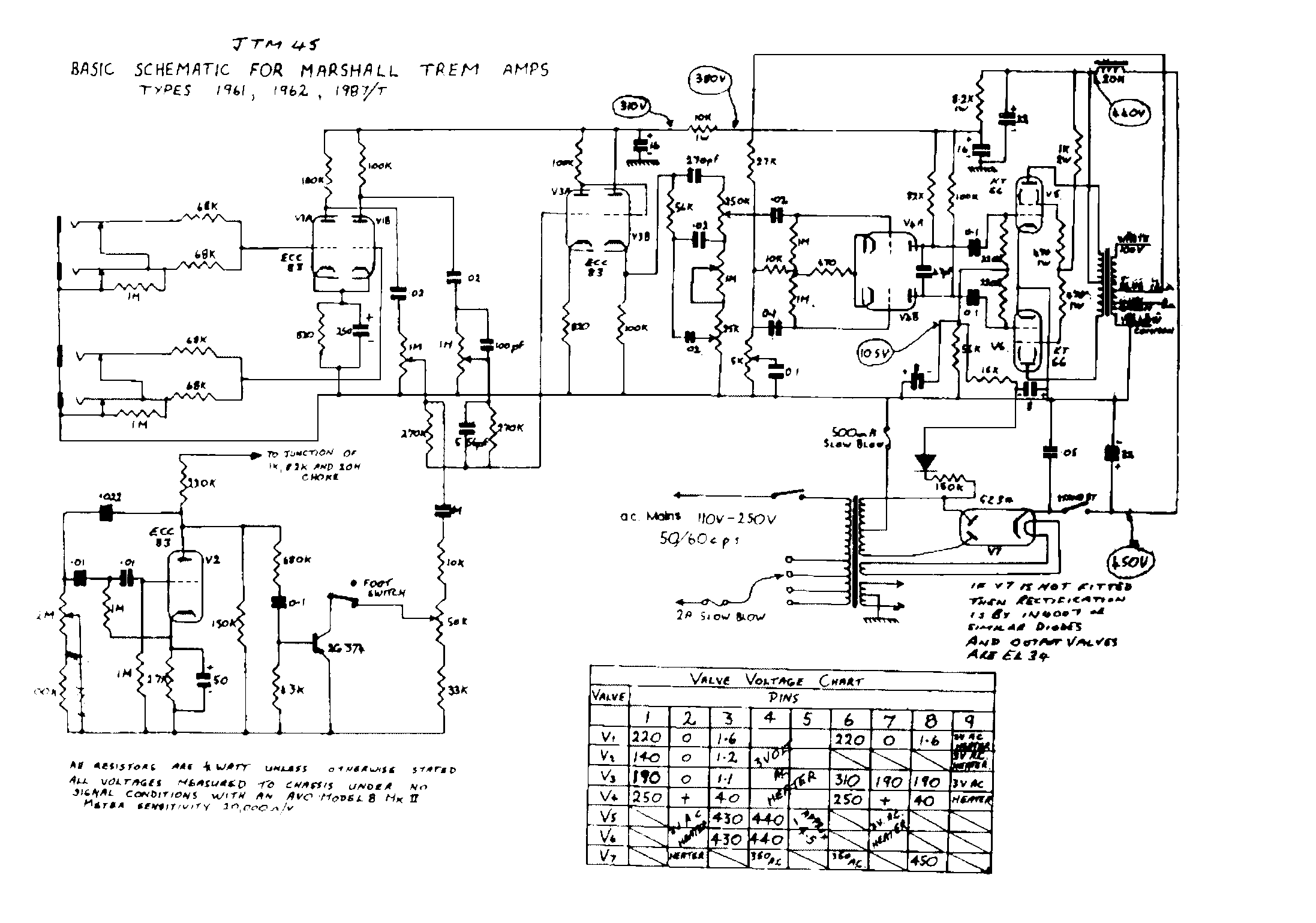
| JTM45 | Marshall trem drawing, types 1961/1962/1987/T | Ladder. Bass wiper looped to its own foot lug |
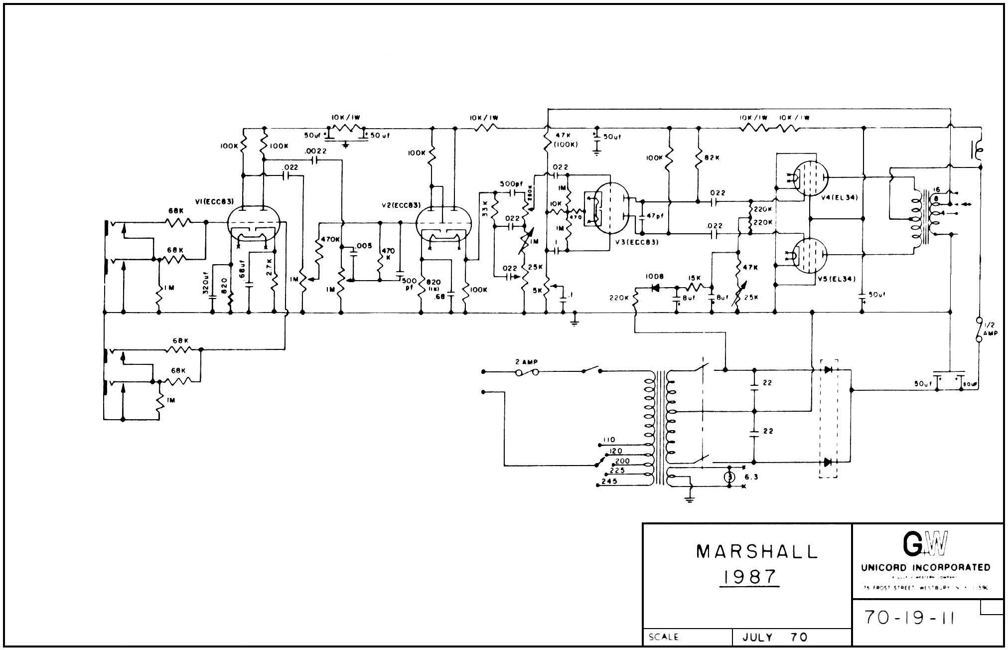
| 1987 | Unicord 70-19-11 | Ladder. Arrow-through-body bass pot |
| 1959 | Unicord 70-6-11 rev B | Ladder, identical to the 1987 |
| AA964 | 045419 schematic and L-FD layout | Ladder, two-knob: fixed 6.8 kΩ leg |
| AB763 | C-FD, both channels | Ladder, two-knob, both channels part for part |
| AA1164 | D 045427 rev A, both sheets | Ladder, two-knob. Layout mounts the 6.8 kΩ on the bass pot's case |
| AA764 | I-FD schematic and layout | Ladder, two-knob: 15 kΩ leg, chassis-mounted at the Bass control |
| 5F4 | C-EG | Neither — a split treble/bass network |
The 5F6 is the strongest single witness, because it exists twice. Its schematic page and its factory layout page were drawn by different hands for different purposes, and they agree: on the schematic the 250 pF and the 56 kΩ both leave the cathode follower's output, the first 0.02 µF lands on the node carrying the treble pot's lower lug, and the treble wiper alone goes on to the phase inverter; on the layout page the bass pot's wiper is strapped into that same treble-lug node, the middle pot's wiper is fed from the second 0.02 µF eyelet, and one lead — the treble wiper's — leaves for the coupling capacitor. A layout sheet cannot be ambiguous about a pot: it has to say which lug each wire lands on, because a person with a soldering iron is going to follow it.
The 5F6-A prints the same network, schematic and layout alike, with one change from the 5F6: the middle pot's foot runs straight to ground, because the presence control moved from the tone stack's ground leg to the phase-inverter tail. Reading that layout page closely paid a second dividend — it marks the Treble pot 250K LIN., a taper the archive had been recording as undocumented.
The three Marshall drawings print the same ladder with British values — a 56 kΩ slope and 270 pF on the JTM45, 33 kΩ and 500 pF on the 1987 and 1959. Each draws the bass pot as a rheostat in its own idiom: the JTM45 loops the wiper back to the foot lug, the two Unicord sheets use the arrow-through-body symbol. The 1987 and the 1959 are wire-for-wire identical here; whatever separates a 50 W head from a 100 W one, it is not this network.
The blackface two-knob sheets — AA964, AB763, AA1164, AA764 — draw the same ladder with the middle pot replaced by a fixed leg and a 100 kΩ slope: 6.8 kΩ on the two Princetons and the Deluxe Reverb, 15 kΩ on the Champ. The AA964 exists as schematic and layout, and both agree. The AB763 draws it twice, once per channel, part for part. The AA1164's layout sheet mounts the 6.8 kΩ on the bass pot itself, grounded to its case — a detail only a layout page can carry — and the AA764's mounts its 15 kΩ off the board at the Bass control, the same idiom.
The tweed Super draws a third network — and its chart stops fighting
The 5F4 is not a two-knob cut of the Bassman ladder. Its C-EG drawing puts treble and bass on two separate branches off the cathode follower and recombines them at the output: 250 pF into a 1 MΩ treble pot whose cold end reaches ground through 0.01 µF and whose wiper is the output; and, on the other branch, a 0.1 µF coupler into a node carrying a 220 kΩ leak, then 100 kΩ in series into the bass pot's wiper, with one end lug on 0.005 µF and the other grounded outright, and 220 kΩ from that injection node back to the output. There is no slope resistor and no shared capacitor ladder. The output node is the phase inverter's grid directly — no coupling capacitor follows.
Reading that sheet properly settled something else on the same page. The 5F4's phase inverter is not a long-tailed pair: the drawing shows a plain cathode-biased driver feeding a split-load cathodyne. Read as the circuit the sheet draws, all five printed phase-inverter voltages are mutually consistent and simulate inside the chart's own ±20 % convention — worst case 16.0 %, at the cathodyne's 1.5 kΩ/56 kΩ junction. An earlier revision of this archive had disputed three of those five as arithmetically impossible. They were not; the impossibility was an artifact of forcing a long-tailed pair onto a cathodyne's printed numbers. The sheet also prints a +1.7 V driver cathode that the earlier reading never transcribed at all, and simulation lands on it to 1.2 %.
(The 5F4's V2A gain-stage pair remains disputed, on separate and genuine arithmetic — see the 12AX7 calibration study.)
What the difference does
The wirings are not a notational quibble; they are different networks with different transfer functions. But they are also nearly the same over most of the dial, which is the whole reason the error survives. Both numbers below come from the same solver the tone-stack lab runs, on the 5F6-A's own part values.
| Control setting | Ladder (as drawn) | Joined (textbook) | Gap at 1 kHz |
|---|---|---|---|
| Treble 5 · Middle 5 · Bass 5 | −12.8 dB | −13.8 dB | 0.9 dB |
| Treble 10 · Middle 1 · Bass 9 | −13.5 dB | −23.2 dB | 9.7 dB |
| Treble 5 · Middle 0 · Bass 0 | −17.2 dB | −100.7 dB | 83.5 dB |
| Treble 10 · Middle 0 · Bass 0 | −12.3 dB | −100.9 dB | 88.6 dB |
At five all round the two curves lie a decibel apart — inside the tolerance of the capacitors these networks are built from, and well inside what anyone would notice by ear. Across the whole-number dial settings with neither Bass nor Middle at zero, the worst disagreement at 1 kHz is 9.7 dB, at Treble 10 · Middle 1 · Bass 9 — the second row above. That bound belongs to the detent grid, not to the networks: below the first detent the curves part company smoothly, and sliding Bass and Middle together toward zero walks the gap up without a ceiling into the last two rows. Go to the stops and the two networks stop resembling each other at all.
The stops are where the wiring shows. Wind Bass and Middle both to zero. In the ladder the middle pot's full 25 kΩ track still stands between the network's foot and ground — the Middle control slides the capacitor's injection point along that track rather than shortening it — so the output is propped up: the curve bottoms out about 31 dB down at the low end of the plotted band and sits 17 dB down at 1 kHz. In the joined form the output rides both wipers, so Bass at zero ties the output to the top of the mid leg, and Middle at zero puts that node on ground. The output goes with it: about 105 dB down. A tone stack that falls silent when two of its three controls reach zero is a strong claim about an amplifier, and none of these drawings makes it.
The shape moves too, not just the floor. With Bass at 10 and the others at five, the ladder's deepest point sits near 710 Hz; the joined form puts its minimum near 2.1 kHz on the same parts.
The blackface two-knob circuits are the quiet case, and instructive for it: with a fixed 6.8 kΩ leg permanently in the ground path, neither wiring can collapse, so the floors differ by barely a decibel (−29.3 dB against −30.5 dB with Bass at zero) even though the level at 1 kHz still differs by 9 dB. A network that never reaches its own failure mode hides the error indefinitely.
Hear the curve yourself. Each preset in the tone-stack lab is solved with the wiring its own sheet draws: 5F6 · 5F6-A · JTM45 · 1987 · 1959 · AA964 · AB763 · AA1164 · 5F4. Set Bass and Middle to zero on any three-knob preset and watch the curve stop around thirty decibels down instead of falling off the chart. Two more drawings — the AA764's and the AB165's — are read and gated like the rest; their parts are not yet built into lab presets.
Why the error propagates
The joined network is not a stupid mistake. It is a good idealisation: it is symmetrical, it is easy to analyse by hand, it draws more neatly, and — the decisive part — it sounds almost identical anywhere a player actually leaves the knobs. An error that only appears at the ends of the travel of two controls at once is an error that no amount of listening will find.
So it copies forward. And this archive is not entitled to say that from the outside, because it made exactly the same mistake, by exactly the same mechanism, and the mechanism is worth writing down.
The wrong network entered here from a redraw, not a source. One of this archive's own early board drawings captioned its tone capacitors as mounting at the pots and left them off the drawing "for legibility"; its pot runs were convention rather than sheet reading. A later pass took that drawing as the anchor and rewired nine schematics to match it. Two of those nine — the 5F6 and the AA964 — had been drawn from their factory layout sheets and carried the correct ladder already. The rewrite overwrote them. The evidence that would have stopped it was inside the archive, in its own drawings, and it lost to the convention.
That is the whole propagation mechanism in miniature. A secondary source is easier to consult than a factory drawing; a tidy network is easier to redraw than a messy one; and when the tidy version and the drawing conflict, the tidy version wins unless someone goes back to the lugs. The fix is not cleverness. It is going back to the lugs.
Method
Reading. Each published drawing was fetched from the archive that holds it and read at 300–400 dpi around the tone-control region, tracing each pot terminal to what it connects to. Layout pages were read alongside schematic pages wherever both exist, because a layout page cannot be vague about which lug a wire lands on. No factory drawing is reproduced, traced, or rehosted here; the figures above are original artwork drawn from the facts read.
Plotting. The lab writes each network as a list of two-terminal elements between numbered nodes and solves it by nodal analysis — a complex admittance matrix per frequency, Gauss–Jordan with partial pivoting — with the driving stage modelled as an ideal source behind its own output resistance. Component values are read from each circuit's own bill of materials, never typed into the page.
Cross-check. The browser solver was checked against independent ngspice AC
sweeps of the same element lists, 10 Hz–100 kHz at 40 points per decade, for the
joined reference form, the ladder in both its mid-leg forms, and the 5F4's split
network: worst-case disagreement 5 × 10⁻⁵ dB. The −30.8 dB ladder floor and the
−104.7 dB joined floor quoted above were each reproduced by ngspice to within
0.1 dB. That cross-check is committed, not archival:
check-tonestack-spice.mjs
rebuilds the element lists, runs the ngspice sweeps, and re-derives every
decibel and hertz figure this study prints, on every push — so the numbers
above cannot drift from the solver that produced them.
Gating. A drawing and a published curve can drift apart silently, so they
are tied together in continuous integration.
check_tonestack_wiring.py
reads
the reference designators out of the site's own preset table — and out of a
companion table carrying the multi-knob networks the lab does not yet plot —
walks the nets in each circuit's schematic file, and asserts the node set of
the wiring each declares: treble-wiper-only output, bass wiper strapped to an
end lug, mid capacitor on the wiper, and no two stack nodes shorted. It
currently reports 13 of 13 — the nine multi-knob presets, the AB763's vibrato
channel, the AA764's stack, and both of the AB165's channels. A schematic edited
back toward the joined network, in any of the eleven circuits read at lug level
and on either channel of the two that draw the ladder twice, fails the build.
Sources
Every drawing read for this study, cited as held by its archive. Nothing is rehosted.
- Fender Bassman 5F6 (F-EG), schematic and layout pages — el34world.com
- Fender Bassman 5F6-A (I-EG), schematic and layout pages — el34world.com
- Fender Super-Amp 5F4 (C-EG) — el34world.com
- Marshall factory drawing, Basic schematic for Marshall trem amps, types 1961, 1962, 1987/T (JTM45) — drtube.com
- Marshall 1987, Unicord drawing 70-19-11, July 1970 — drtube.com
- Marshall 1959, Unicord drawing 70-6-11 rev B, July 1970 — el34world.com
- Fender Princeton-Amp AA964, schematic (drawing 045419) — el34world.com — and layout (L-FD) — el34world.com
- Fender Deluxe Reverb-Amp AB763 (C-FD), schematic and layout — el34world.com
- Fender Princeton Reverb-Amp AA1164 (drawing D 045427 rev A), both sheets — el34world.com
- Fender Champ-Amp AA764 (I-FD), schematic — el34world.com — and layout — el34world.com
- Fender Bassman-Amp AB165 (D-FE), schematic and layout — the ladder drawn twice, once per channel — el34world.com
Status
Adopted corpus-wide on 2026-08-03. All eleven schematics draw the network their own sheets draw; the board diagrams and their captions follow the same sheets; each amp's notes state the wiring in words; and every lab preset declares which wiring it is solved with. The wiring gate reports 13 of 13, the layout-to-netlist equivalence gate is green, and the 5F4 is verified against its printed chart with its phase-inverter dispute withdrawn.
Five multi-knob circuits in the archive have not had this reading yet — the brown Super 6G4 and Pro 6G5, the blackface Bassman AA864, the tweed Pro 5E5-A and the tweed Bassman 5E6-A. Their schematics draw a tone network, but none is declared to the wiring gate, so none is held to what this study found. Each is a draft circuit and says so on its own page; a reading pass moves it into the count above, and any that turns out to draw something else gets written up here the way the 5F4 was.
The joined network is kept in the solver, and only there — as the reference form this study is written against. No preset uses it, because no drawing this archive has read draws it. If a factory sheet turns up that does, it gets a preset, a page, and a correction to this study.
Sources are linked above and none are reproduced. Curve values are stated as the corpus's own solver computes them from each circuit's published part values, cross-checked against ngspice. Pipeline and models are CC0.